This site uses cookies to improve your experience. To help us insure we adhere to various privacy regulations, please select your country/region of residence. If you do not select a country, we will assume you are from the United States. Select your Cookie Settings or view our Privacy Policy and Terms of Use.
Cookie Settings
Cookies and similar technologies are used on this website for proper function of the website, for tracking performance analytics and for marketing purposes. We and some of our third-party providers may use cookie data for various purposes. Please review the cookie settings below and choose your preference.
Used for the proper function of the website
Used for monitoring website traffic and interactions
Cookie Settings
Cookies and similar technologies are used on this website for proper function of the website, for tracking performance analytics and for marketing purposes. We and some of our third-party providers may use cookie data for various purposes. Please review the cookie settings below and choose your preference.
Strictly Necessary: Used for the proper function of the website
Performance/Analytics: Used for monitoring website traffic and interactions
I have a problem, that I cannot bring together working PAT and Port forwarding on a Cisco router. Here is my topology: Explanation to topology: Start connection sourced by 192.168.1.1 Then router forwards connection to destination ip address 192.168.2.2 with destination port 1234 and destination ip address 192.168.1.2
With the settings I have specified in my topology, I can bring up Tunnel 10 and Tunnel 20, but I cannot ping the other ends of the tunnels. For example, from the router with IP 172.16.1.1, I am using Cisco routers. Can you help me with this topology? I cannot ping 172.16.1.2. The same issue occurs with Tunnel 20.
Network Setup: Devices Involved: A Cisco 2900 router. Topology: The virtual Layer 3 switch is connected to the physical network via a hub. Both the Cisco router and the physical Layer 3 switch are also connected to the same hub. Router Priorities: Properly configured. A physical Layer 3 switch running FRR.
I want to ping from a computer located in SITE C to computers in SITE A and SITE B within the topology. 24 | | [Router] [Router] | | 192.168.2.0/24 24 | | [Router] [Router] | | 172.16.11.0/24 24 | [Router C] | 192.168.3.0/24 What VPN technologies can I use to overcome these problems? 24 192.168.1.0/24
I got a router on a stick and I want to optimize it by reducing its cost and also the configuration costs This topology is to facilitate inter Vlan routing so Vlan1 can communicate with Vlan2. The question is how will this topology be optimized. The topology is illustrated in the figure
You can see the topology in the picture below. pointing to the routers subinterface). Ive configured the management VLAN on the switch to be VLAN 999 to separate the management traffic from user traffic. Ive also configured SVI 999 with an IP address of 10.10.10.2/24.
Starting from the following network topology: Internet ISP Cable Router Firewall Router rest of the network / multiple VLANs (port forwarding) | DMZ I had to expose two VLANs over the internet through VPN for two groups of users.
I'm trying to connect 4 networks with 1 router, i created 2 sub-interfaces in the router, when i tried to create the 3rd sub-interface i got this output "%Cannot create sub-interface", this is my topology: This is my Router's configuration: hostname Router ! ip cef ip ipv6 cef ! spanning-tree mode pvst !
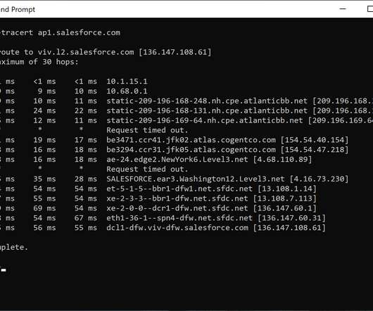
Not as difficult as time travel, but it’s difficult enough so that for 30+ years IT professionals have tried to skirt the issue by adding more bandwidth between locations or by rolling out faster routers and switches. Each switch and router we pass through introduces a bit of latency that adds up quickly. How latency is measured.
Why do we need to create site-to-site VPNs or some sort of modern SD-WAN topology connecting all our branches when almost all traffic goes to the public internet and the cloud? We still need to connect our infrastructure to the public internet, so the enterprise WAN is still about routers, circuit IDs, and perimeter firewalls.
Notice above that the routers used in the connection are looking pretty snappy. If you don’t have fancy tools that tell you who is communicating through the router, take all other internet capable devices offline. If you have access to your local router, login and see if you can give connections to your SaaS application a priority.
In this blog, we will explore what static routes are, how they differ from dynamic routes, and how to configure them on routers like Cisco devices. This feature in networks predicts and stabilizes the topology. This characteristic makes them efficient for routers with limited processing capabilities.
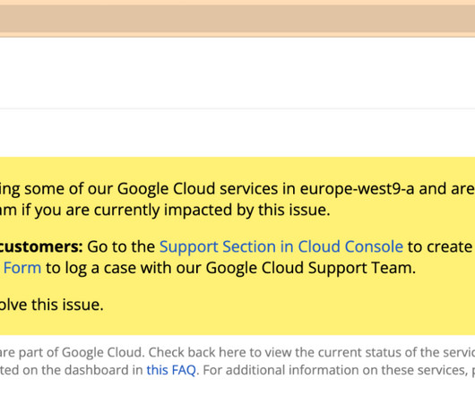
Kentik Cloud users can now access the new Kentik Map for Google Cloud to automatically visualize detailed Google Cloud and hybrid cloud infrastructure topology. In addition, the map visualizes Dedicated Interconnect attachments, VM interfaces, and VPN gateways with their associated on-prem and cloud routers.
This includes the ability to: Dynamically adjust to changes in network topology Detect and respond to outages Route around faults in order to maintain connectivity and service levels. It is used to maintain network connectivity by helping routers find the best path for traffic to travel through.
VXLAN EVPN Basic Topology EVPN Route Type The EVPN control plane advertises the following types of information: Ethernet auto-discovery (AD) routes are route type 1. Ethernet segment routes, or route type 4, are used to broadcast the length of the IP address, the originating router's IP address, and the Ethernet segment identifier.
The physical topology continues to expand with relentless traffic growth, and a constant stream of new technologies like SDN, Clos architectures, and cloud interconnects make it even harder to understand how services traverse the network between application infrastructure and users or customers. Let’s face it — today’s networks are complex.
If the VPN gateways cannot generate flow or Syslog with traffic, the next richest data comes from the edge routers or switches near the VPN devices. This data is useful for Kentik’s automated capacity planning workflows and building topological maps (layer 2 and layer 3 connectivity).
Be it power supplies, servers, routers, load balancers, proxies, or any other physical and virtual network components, the horizontal scaling that redundancy provides is the ultimate safety net in the presence of failure or atypical traffic demands.
Given that we only have one IP active in on each node, the next step was to have this landing node act as a router for inbound BGP connections with policy routing as the high-level design. On top of that, since our BGP nodes were identical, the distribution of sessions should be balanced. IPv6 peerings are starting to outgrow a single node.
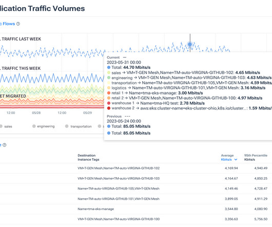
That includes adding in high-value data such as threat feed and threat modeling, routing, topology, and other important networking information to model answers to difficult questions. Flow can also be used to understand consumption of bandwidth in a more granular manner.
Internal Envoy routers allow communication between the global cell and replicated cells. Enable the zone-aware routing feature for internal Envoy routers Make the solution more extensible to support HTTP1/HTTP2/gRPC traffic using other domains beyond DDSD. This approach enables us to reduce the blast radius of a single-cell failure.
That includes adding in high-value data such as threat feed and threat modeling, routing, topology, and other important networking information to model answers to difficult questions. Flow can also be used to understand consumption of bandwidth in a more granular manner.
Traditional WAN Overview WANs were designed to connect distributed corporate locations, traditionally, with WAN routers at each location. These WAN routers defined the network boundaries and routed traffic to the appropriate destination. This generates significant cost savings when compared to traditional WANs.
MPLS circuits are extremely expensive, with a router required at each site, access circuits, bandwidth cost, and the associated CoS fee. Managing hybrid WAN topologies, which combine MPLS and the Internet, with legacy approaches to branch networking is often costly and ineffective as well.
Under this model, network topology is highly variable, creating a complexity that can mask root causes and make proactive availability configurations a highly brittle point of the network. A single misconfiguration, such as an incorrect firewall rule or a misrouted connection, can trigger a cascade of failures.
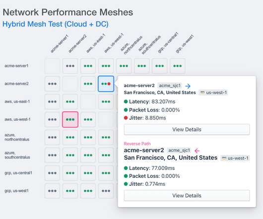
There are appliances, there’s downloadable software, but there’s been no SaaS option that gives them the basic network visibility that they want, with an understanding of their topology and how networks interconnect, but also gives them the context of what the performance of that traffic is. It gets back to that age-old “is it the network?”
The policies and routing intelligence would run in one or more servers (controllers), which would instruct the networking elements forwarding the packets (switches and routers). SDNs first were introduced in the data center with the goal of increasing network by separating the data plane from the control plane.
ingested into the Kentik Data Engine with two new fields that represent the Device (router) and Site (PoP) where that flow will exit the network to an adjacent autonomous system (AS). We can’t yet see where (geographically or topologically) the traffic from XYZ is entering the network, and we also can’t see where it egresses to the next hop.
Kube-router (CloudNativeLabs) - provides a Linux LVS/IPVS-based service proxy, a Linux kernel forwarding-based pod-to-pod networking solution with no overlays. It’s responsible for the reliable delivery of requests through the complex topology of services that comprise a modern, cloud-native application.
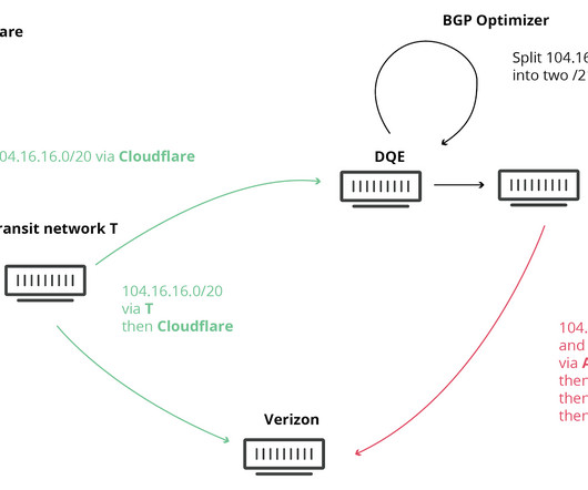
In this incident, a software bug caused a router to announce a large part of the IP address ranges present in the global routing table as if they were originated by AS7007. Two competing methodologies, RPSL and RPKI, are used to inform the defensive configuration of routers.
Topology Aware Routing is a feature of Kubernetes that prevents cluster traffic within one availability zone from crossing to another availability zone. TL;DR: AES-GCM is great, as long as every nonce (mnemonic: number used once) is truly unique. Once a nonce is reused, AES-GCM completely falls apart.
Let's say, that there is a following network topology: As seen on the drawing, the router named as30-r1 is connected to IXP LAN with network 10.81.80.0/22 count 1 sends an ICMP echo request message correctly to as10-r1 router. Accepting these routes may create a black hole for connectivity to the IXP LAN. 24 user 0 192.168.5.1
We organize all of the trending information in your field so you don't have to. Join 5,000+ users and stay up to date on the latest articles your peers are reading.
You know about us, now we want to get to know you!
Let's personalize your content
Let's get even more personalized
We recognize your account from another site in our network, please click 'Send Email' below to continue with verifying your account and setting a password.


Let's personalize your content