This site uses cookies to improve your experience. To help us insure we adhere to various privacy regulations, please select your country/region of residence. If you do not select a country, we will assume you are from the United States. Select your Cookie Settings or view our Privacy Policy and Terms of Use.
Cookie Settings
Cookies and similar technologies are used on this website for proper function of the website, for tracking performance analytics and for marketing purposes. We and some of our third-party providers may use cookie data for various purposes. Please review the cookie settings below and choose your preference.
Used for the proper function of the website
Used for monitoring website traffic and interactions
Cookie Settings
Cookies and similar technologies are used on this website for proper function of the website, for tracking performance analytics and for marketing purposes. We and some of our third-party providers may use cookie data for various purposes. Please review the cookie settings below and choose your preference.
Strictly Necessary: Used for the proper function of the website
Performance/Analytics: Used for monitoring website traffic and interactions
The router can ping the DHCP server, but end devices connected to the router cannot obtain an IPaddress. Heres my setup and what Ive tried so far: Network Setup: DHCP Server: IP: 192.10.0.2 Main Switch: Connects to the DHCP server and all routers. Main Switch: Connects to the DHCP server and all routers.
InterVLAN traffic is routed through the gateway which has IPaddress in every VLAN that can be used as a default route on the servers. There are multiple VLANs set up on the servers, so interface mode on the switch is set to trunk. Traffic inside a certain VLAN goes through the switch.
I have a comcast business router and the only thing behind it is an unmanaged switch. All of the IPaddresses on my PCs are 192.168 but when I log into the router everything shows 10.0 addresses.
These sub-interfaces are configured with IPaddresses and OSPF. Could this cause issues with other routers or implementations? The MTU of the physical interface has been increased, but the MTU of the VLAN interfaces has not been changed. The MTU remained unchanged when I checked the OSPF hello packets in Wireshark.
So, if I want to ping from Desktop 0 to Network 4 PC, the packet would first go to the Default Gateway Firewall(DG FW), then to Network 4 ASA FW, then to Network 4 Router, then to Network 4 L2 Switch, then to Network 4 PC, and lastly obtain the ping reply coming the same way it came in. 24 via 172.21.1.253 Network 4 Router: 192.168.1.0/24
Ive also configured SVI 999 with an IPaddress of 10.10.10.2/24. pointing to the routers subinterface). Ive configured the management VLAN on the switch to be VLAN 999 to separate the management traffic from user traffic. The default gateway is already configured on the switch as well (which is 10.10.10.1,
Box routers can be replicated between Linux hosts. Box assigns - and reserves - static IPaddresses in the same network segment of its LAN to the VPN interfaces of the clients. The addresses are, quite obviously, outside the DHCP range. I'm wondering whether a Wireguard setup similar to that used in the Fritz!Box
I have a problem, that I cannot bring together working PAT and Port forwarding on a Cisco router. with destination port 1234 and destination ipaddress 192.168.1.2 Then router forwards connection to destination ipaddress 192.168.2.2 When forwarding the packet out of f0/0 to ipaddress 192.168.2.2
Problem Statement: I have two houses ( House1 and House2 ) connected via a WireGuard VPN setup, with routers acting as intermediaries. I need to configure the network so that all internet-bound traffic from a laptop in House2 routes through House1's internet connection (specifically RouterA's public IP ).
So here's the situation that I have at my workplace (local municipality): I have received from my ISP a static IPaddress with a provided gateway, which all works normally when I input it into my router (ISP's router works in bridge mode).
How can I achieve reachability from vlan terminated on the L3 switch to routed port on the router, FW? int vlan 10,50 are the SVI's on L3 switch vlan 10 - 10.0.10.254 /24 vlan 50 - 10.0.50.254 /24 vlan 50 is the native vlan on trunk link towards (router, FW) Routed port is configured on the physical interface with 10.0.50.1/24
24 | | [Router] [Router] | | 192.168.2.0/24 24 | | [Router] [Router] | | 172.16.11.0/24 24 | [Router C] | 192.168.3.0/24 What VPN technologies can I use to overcome these problems? SITE A SITE B [PC] [PC] 192.168.1.0/24 24 192.168.1.0/24 24 192.168.2.0/24 24 172.12.12.0/24 24 / / [ WAN ] / __/ | 172.11.10.0/24
the devices connected to LAN 1 have an IP adress of (192.168.0.x), x), and the devices connected to LAN 2 have IPaddress in the form of (192.168.1.x). we have 2 different LANs, a printer and some PCs are connected to LAN 1 via an ethernet cable, and some PCs are connected to LAN 2, also via an ethernet cable.
How do I write a named extended ACL which will allow for traffic between a DNS from a LAN (IPaddress) to a DNS server at (IPaddress), ping from a host PC (IPaddress) to any destination and allow for telnet packets from a telnet server with any source address going to any destination?
I have this network when the network tries to communicate with the routers it fails. Router>enable Router# Router#configure terminal Enter configuration commands, one per line. Router>enable Router# Router#configure terminal Enter configuration commands, one per line. End with CNTL/Z.
I'm trying to connect 4 networks with 1 router, i created 2 sub-interfaces in the router, when i tried to create the 3rd sub-interface i got this output "%Cannot create sub-interface", this is my topology: This is my Router's configuration: hostname Router ! ip cef ip ipv6 cef ! no ipaddress !
I have two private IPaddresses, want to make them NAT to 203.0.113.0/2 2 public IPaddress. WAY 1 : Static NAT (2 ipaddresses NATted to one by manually) WAY 2 : PAT (Router gives port number for each device randomly) Question is that : Why doesn't router apply the same things on Static NATting?
interface GigabitEthernet0/0/0 description SAF WAN ipaddress X.139.250.X ip nat outside negotiation auto ! interface GigabitEthernet0/0/1 description LAN ipaddress X.21.10.X ip nat inside negotiation auto ! interface GigabitEthernet0/0/2 no ipaddress shutdown negotiation auto ! X 255.255.0.0
If I assign a static IP on the device level that is within the DHCP range of the network it's on, but don't reserve its address on the DHCP server, will the device lose its IPaddress or be disconnected if the router restarts?
For reasons that are not important, we have a customer that wants to ensure that it can not work on an actual IP network and only direct. So, we changed our firmware so that the fixed IPaddresses are 127.0.0.0 Are there any IPaddresses that will not flow through a switch? and 127.0.0.1. Thank you.
The PCs can ping the other ipaddress just fine except the 172.16.99.x. Below is my router and switch configuration: Johor-RT (ROUTER): Current configuration : 1690 bytes ! interface Tunnel0 ipaddress 192.168.3.118 255.255.255.252 mtu 1476 tunnel source Serial0/1/1 tunnel destination 160.249.3.58 ! !
The problem is that when ESXi is down it takes down all the network with it, so I have to boot up another router to log in to it. ip dhcp pool mgmt network 10.0.0.0 default-router 10.0.0.1 domain-name LAN ip dhcp pool trusted network 10.0.10.0 default-router 10.0.10.1 ip dhcp pool untrusted network 10.0.20.0
I would really appreciate ISP Int g0/0 ip add 2.2.1.1 255.255.255.252 no shut Int g0/1 IP add 2.2.2.1 255.255.255.252 no shut int g0/2 ip add 2.2.3.1 255.255.255.252 no shut int g0/3 ip add 4.4.129.1 255.255.255.252 no shut int g0/3 ip add 4.4.128.1 interface G0/0 nameif outside security-level 0 ipaddress 2.2.1.2
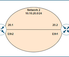
In one of the articles , we talk about layer 2 switching where switches build the MAC address table to decide where to forward frame based on the destination MAC address. Here well see how a layer 3 switch or a router transmit packets between different networks using the layer 3 destination address.
The global gateway is set to the IP of the router. (I I tried setting to the interface of the VLAN that has the network devices but it did not accept that IP) On VLAN10 I have a port that goes to my firewall / router (Watchguard M300). L3 MAC Address. console#show ip brief Default Time to Live. 255.255.255.0
share one router with a single public IPaddress. When a device wants to access the internet, it sends a request to your router. The request contains the device's private IPaddress. The router’s NAT process replaces the private IP with the router’s public IP.
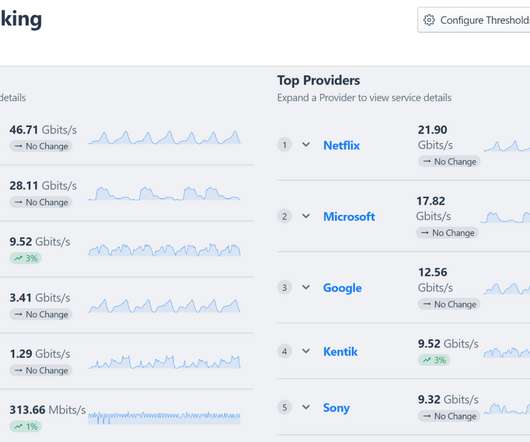
Back in the 1990s, NetFlow was introduced on Cisco routers as a means to collect information about IP network traffic as it enters or exits an interface. Source IPaddress. Destination IPaddress. IP protocol. IP type of service. Source port for UDP or TCP, 0 for other protocols.
We are bringing our own /24s -- our provider will announce our IP blocks and then statically route our IP space to one of the usable IPaddress in the /29 range they supply. Our new colo space has 2x connections coming into our rack from our provider - these will be used as redundant uplinks.
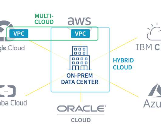
Vendor’s data centers have private links to their own routers which are set up in AWS Direct Connect Locations. Direct Connect Location: a high-speed AWS network traffic exchange center that contains both AWS Direct Connect routers and vendor’s routers. The VGW is a VPC edge router for exposing internal traffic.
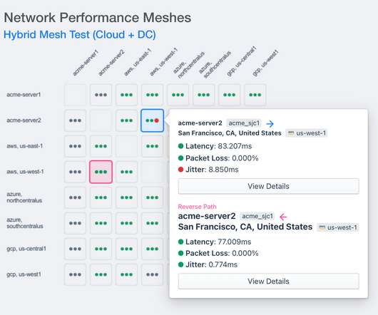
Not as difficult as time travel, but it’s difficult enough so that for 30+ years IT professionals have tried to skirt the issue by adding more bandwidth between locations or by rolling out faster routers and switches. Each switch and router we pass through introduces a bit of latency that adds up quickly. How latency is measured.
The critical context that enables teams to ask questions about users, applications, and customers (and not just IPaddresses and ports). Traditional WAN : WAN access switches, integrated services routers, cloud access routers. The key telemetry types to shine a light on network activity and health.
Bad hardware (the switch or router port). Overwhelmed router. Congestion in the form of high-connection utilization or an overworked router in the path is another common source of trouble. TCP traceroute : A TCP trace reaches out to every router in the path to a target destination. Miss-matched duplexing (full vs. half).
According to a statement published last night, Facebook Engineering wrote, “Configuration changes on the backbone routers that coordinate network traffic between our data centers caused issues that interrupted this communication.” tfbnw.net — which is another router inside AS32934 that belongs to Facebook. So what happened?
It is a globally recognized certification that helps you recognize your skills in the following areas: Network fundamentals and access IP connectivity IP services Security fundamentals, and more In short, you get to learn how to configure and operate routers and switches. We also usually address the CCNA as CCNA 200-301.
Or, perhaps one or more of the 10-20 routers in the path needed to reach the destination gets busy for a hundred milliseconds or so. Domain lookup time : When a connection is made to a domain, the local operating system must first reach out to the DNS to resolve that hostname to an IPaddress. Where is the DNS?
Route type 2, or the advertisement route for MAC/IP: This broadcasts the MAC and IPaddresses of the endpoints, or VTEPs, as well as endpoint reachability data. Ethernet segment routes, or route type 4, are used to broadcast the length of the IPaddress, the originating router'sIPaddress, and the Ethernet segment identifier.
Replacing cEdge in Cisco SDWAN environment Replacing the cEdge router with another cEdge through an RMA process for Cisco SDWAN , we need to put the basic configuration on the new RMA router and should be reachable via vManage. It is important that you should know the new router serial number should be learned to vManage NMS.
Microsoft has since blamed the outage on a flawed router command which took down a significant portion of the cloud’s connectivity beginning at 07:09 UTC. During this re-computation process, the routers were unable to correctly forward packets traversing them.
The Mirai botnet was first discovered back in 2016, but has continued to persist and abuse common vulnerabilities and exposures (CVEs) on IoT devices, including home routers and many other network-connected devices. These addresses were apparently port scanning IPaddresses that belonged to the company sending the letter.
In this blog, we will explore what static routes are, how they differ from dynamic routes, and how to configure them on routers like Cisco devices. This characteristic makes them efficient for routers with limited processing capabilities. What are the key features of static routes? How can I configure static routes?
When the network team investigates, they may see all types of problems such as ingress and egress points with no security policies, internal communications routed over internet gateways, abandoned gateways, abandoned subnets with overlapping IPaddress space, or VPC peering connections with asymmetric routing policies.
We organize all of the trending information in your field so you don't have to. Join 5,000+ users and stay up to date on the latest articles your peers are reading.
You know about us, now we want to get to know you!
Let's personalize your content
Let's get even more personalized
We recognize your account from another site in our network, please click 'Send Email' below to continue with verifying your account and setting a password.


Let's personalize your content